
In this lab exercise, we’ll learn how to connect external parts to our Raspberry Pi using its pins, specifically:
A major advantage of prototyping using single board computers is that we can take advantage of existing libraries to easily build attractive, user-friendly interfaces to our circuits. In this exercise, we’ll see an example of that.
Finally, we’ll also practice using three measurement instruments - a digital multimeter, the Analog Disovery 2, and the piscope software logic analyzer - to understand the circuits we are building around the Raspberry Pi.
This section contains some brief notes about the parts used in this lab.
Find these parts, and set them aside until you need them:
A diode has two pins:
When a positive voltage greater than a minimum forward voltage is applied across its pins, then current is conducted through the diode, from the anode to the cathode. Otherwise, no current is conducted.
A light-emitting diode (LED) emits light when it is conducting current.
The voltage drop across the LED will be equal to its forward voltage (listed in the datasheet). Typically, the voltage drop increases with the frequency of the light, so that a red LED usually has a voltage drop around 1.8-2.2V, but a blue or violet LED is likely to have a voltage drop around 3.0-3.4V.
The LED datasheet describes the maximum continuous forward current that the LED can tolerate. A current limiting resistor should be used in series, to limit the current so that it does not exceed this value.
A push button is a kind of switch, with terminals that are either connected or not connected depending on whether the button is pressed. A momentary push button switch, like the one we’ll use today, does not maintain its state; it is actuated only while you are actively pressing it.
The buttons we will use today are normally open buttons, with four pins. The four pins are arranged as shown below:
Pin 1 is always connected to pin 2, and pin 3 is always connected to pin 4. The switch is open and there is no current flow between the first pair of pins (1-2) and the second pair of pins (3-4), unless the button is being pressed. When the button is pressed, all of the pins are electrically connected and current can flow freely between them.
When the pins on the switch are not marked, we can use a handheld multimeter with a continuity setting to identify which pins are internally connected, and which are only connected while the switch is actuated.
In this lab, we’ll practice using three measurement instruments -
For more material about these measurement instruments:
Lab report: (Individual work) Which measurement instrument(s) could you use:
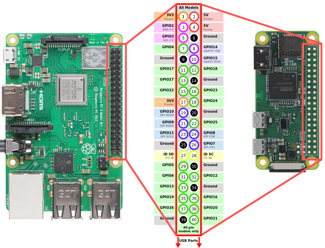
This page is provided here for reference. For an interactive pinout diagram, see https://pinout.xyz.
For this lab, you’ll use the Digilent Analog Discovery 2 measurement instrument, which requires that some software be installed on your laptop.
You can download and install Digilent Waveforms from the Digilent website, if you don’t mind sharing your information with them and letting them send you email. Or if you prefer, I have prepared some direct download links for you instead:
You’ll also need to install some software libraries and applications on your Pi. Use SSH to connect to your Pi, and run these commands in the terminal on your Pi.
This section requires Internet access on your Pi, and will download some software to your Pi. You may prefer to do this over a network connection that is not metered (e.g. you may not want to use your phone hotspot for this, if your cellular data is limited).
First, we’ll make sure we have the latest versions of some software packages that are available through the Raspberry Pi OS package repositories. Start by making sure the package manager has an updated cache, so that it knows which package versions are available:
sudo apt updateThen, install or upgrade packages with
sudo apt -y install i2c-tools build-essential python3-dev \
  python3-pip python3-rpi.gpio python3-pil \
  python3-smbus python3-setuptools minicom git
These may already be installed on your Pi, but if not, or if they’re not up to date, the latest versions will be installed now.
Next, we’ll install Flask. In this lab, you’ll use Flask to host a browser-based user interface for a circuit connected to your Pi.
Install Flask on your Pi with:
sudo pip3 install flask(If it was already installed, that’s fine!)
To make sure that Flask is ready to use, try to import it in Python - run
python3 -c 'import flask'If Flask is installed, you shouldn’t see any output from these commands. If you see an error message instead, ask for further guidance.
Next, we’ll install piscope. Piscope is a software logic analyzer that shows the state (HIGH or LOW) of each of the Pi’s GPIO pins, in real time. We’ll install piscope now for use in this and future lab exercises.
Install the pigpio package, which is used by piscope. In a terminal, run:
wget https://github.com/joan2937/pigpio/archive/master.zip
unzip master.zip
cd pigpio-master
make
sudo make install
This will download an archive containing the source code, extract the archive, change your current directory to the one you just extracted, compile the source code, and then install the compiled code on your system. It will take some time to compile, since the Pi Zero is not very powerful.
To make sure that the installation was successful, run
pigpiod -vThis command should print the pigpio version number and then exit. If you see any error message instead, ask for further guidance.
Then, use
cdto return to your home directory, and install the piscope software:
wget http://abyz.me.uk/rpi/pigpio/piscope.tar
tar xvf piscope.tar
cd PISCOPE
make hf
make install
Then, return to your home directory again:
cdFinally, we are going to download and install a Python script that shows us the mode (INPUT, OUTPUT, or ALT) of every GPIO pin. We will call this script using the command gpio-readall when we need to check pin state.
sudo wget -O /usr/local/bin/gpio-readall https://raw.githubusercontent.com/ffund/gpioreadall/main/gpioreadall.py
sudo chmod a+x /usr/local/bin/gpio-readallOn your Pi, create a new directory in which you’ll save all the code you use in this lab:
mkdir ~/lab-gpioOn your Pi, run
gpio-readallThis should show the pinout of the Pi, with Broadcom numbering, physical pin numbering, and the current mode of each pin.
Take a screenshot showing the full gpio-readall output - this shows the default configuration of the pins on boot.
Also try the
pinoutcommand. This is a useful reference that shows you a color-coded graphical representation of the Pi, with its pinout.
You will need:
Don’t connect your Pi to your circuit yet - you’ll do that in the next section, Connect your Raspberry Pi.
In the next section, you will construct a circuit as shown below, with a “normally open” push button connected to a GPIO input pin using two resistors:

The 10kΩ resistor with one end connected to GND serves as a pull-down resistor. Without this connection to GND, the GPIO input pin would see a “floating” input when the push button is not pressed, with indeterminate results.

With the connection to GND through the 10kΩ resistor, the GPIO input sees a LOW voltage when the push button is not pressed. When the button is pressed (and the switch is closed), the input is HIGH.
The 10kΩ value is large, to avoid pulling too much current when the switch is closed, but is small enough so that we can be sure it will actually pull the input down, even if there is a small leakage current.
The 470Ω resistor between the GPIO pin and the rest of the circuit serves as a current-limiting resistor in case of user error. Suppose we were to accidentally configure the GPIO pin as output, with a LOW value, and press the button (closing the switch). This would create a short circuit between 3.3V and GND. The current-limiting resistor protects the GPIO pin from sinking too much current in this case (the current will be limited to 3.3V/470Ω = 7mA).
Prepare the resistors and the push button on a breadboard, as in the following diagram. (Note that you only need the two pins of the push button that are on the left side; it’s OK if the other two pins are in the ravine, not actually plugged into the breadboard.)

Before you connect your Pi to this circuit, there is one more important step: you must make sure the push button is configured so that that two pins on the left side are not connected internally unless the push button is pressed. You’ll use the continuity mode on your multimeter to verify this.
Follow along with the demo video as you:
If necessary, rotate the push button and test again until you get the continuity results indicated in the figures below.


Lab report: Upload a photo of your breadboard, with the push button and resistors in place. Annotate the photo to indicate which pairs of pins on the push button are always connected internally, and which are only connected when the push button is pressed.
Lab report (Individual work): Draw a schematic of a circuit for the push button switch, but with a pull-up resistor instead of a pull-down resistor. Also answer the following questions about the circuit with the pull-up resistor:
Now, you’re ready to connect your Pi to your breadboard circuit.

Connect your Pi to your circuit as in the diagram:
We’re going to use Piscope to observe button press events as they appear on the input pin. You can follow along with this demo video as you work on this section.
Piscope is a GUI application, so you’ll need to open a VNC connection to your Pi. Then, from the application menu on the Pi (within VNC), open a terminal.
To run piscope you need to have the pigpiod daemon (process that runs continuously in the background) running. In the terminal, run
sudo pigpiodto start the background process. You’ll need this to be running any time you want to run piscope, so if you restart the Pi you’ll have to start pigpiod again.
Note: if you accidentally run sudo pigpiod when the daemon is already running, you’ll see a message:
2020-10-04 22:31:26 initInitialise: Can't lock /var/run/pigpio.pid
Can't initialise pigpio library
This means that pigpiod is already running.
Once pigpiod is running, run
piscope(you can ignore non-fatal errors that appear in your terminal). A new window should open up. Move your mouse over the icons in the menu bar, to see the mouse-over text indicating their functionality. Use the menu to view real-time GPIO status and to pause and restart the view.
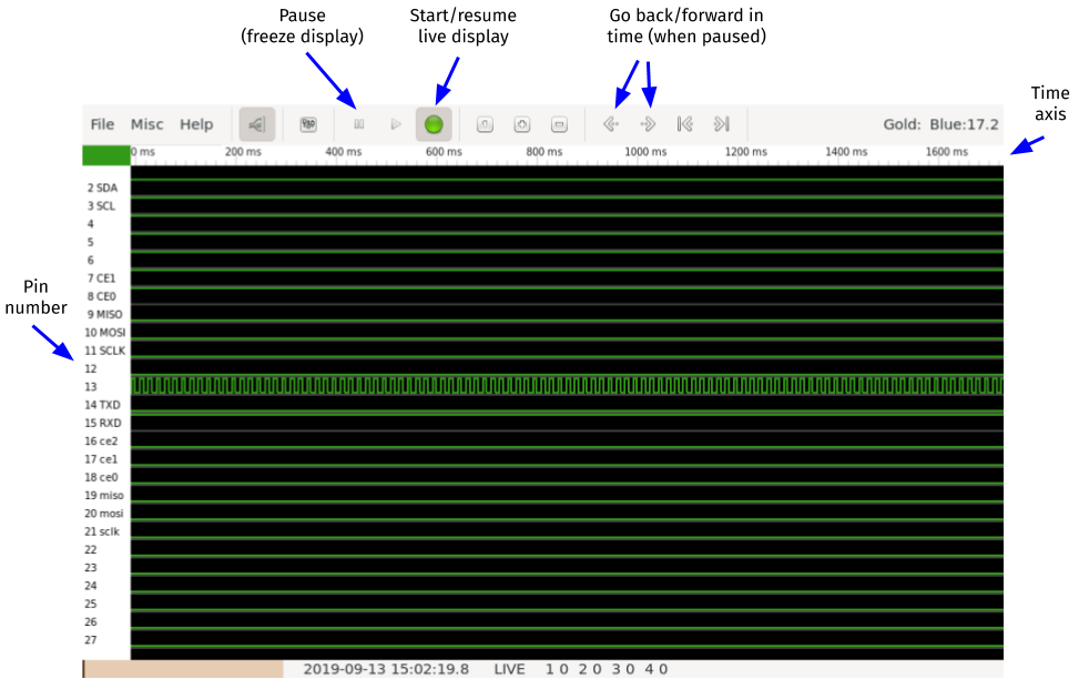
Press the button a few times. Use the buttons in the Piscope menu to find your button press event, and zoom in so that you can clearly see the rising and falling edge on the line.
Lab report: Take a screenshot of the piscope window showing one button press + release, and annotate it to clearly mark:
You can follow along with this video as you work on this section.
Connect your Analog Discovery 2 to your circuit as follows:
Lab report: Take a screenshot of the Scope window showing one button press + release, and annotate it to clearly mark:
We can use the RPi.GPIO library in Python to read the value of the input pin.
First, on your Pi, navigate to the directory you created earlier:
cd ~/lab-gpioThen, create a new file and open it for editing:
nano gpio-input-1.pyPut the following code into this file, then save it and close nano:
import RPi.GPIO as GPIO
import time
import sys

GPIO.setmode(GPIO.BCM)
pin = 17 # BCM17
GPIO.setup(pin, GPIO.IN)

try:
  while True:
    i = GPIO.input(pin)
    print(i)
    time.sleep(1)

except KeyboardInterrupt:
  GPIO.cleanup()
  sys.exit()
Run the Python script with
python3 gpio-input-1.pyThis script will read the value of the input pin every second, in an infinite loop, until you press Ctrl+C. Try pressing the button while this script is running, and observe the output. Then, stop the script with Ctrl+C.
This script uses polling - it keeps on checking the value of the pin. If we just want to be notified when the button is pressed, it’s more effecient to use an interrupt approach instead. This will notify us when the button is pressed, but won’t keep using the CPU to check the value of the pin.
To try the interrupt approach, create a new file and open it for editing:
nano gpio-input-2.pyPut the following code into this file, then save it and close nano:
import RPi.GPIO as GPIO
import time
import sys

GPIO.setmode(GPIO.BCM)
pin = 17 # BCM17
GPIO.setup(pin, GPIO.IN)

try:
  GPIO.wait_for_edge(pin, GPIO.RISING)
  print("Button is pressed")
  sys.exit()

except KeyboardInterrupt:
  GPIO.cleanup()
  sys.exit()
Run the Python script with
python3 gpio-input-2.pyand test it by pressing the button.
This script will block execution of the program until the button is pressed. In other words, the line following the call to wait_for_edge() will only run after the button is pressed (and a rising edge is detected).
Note: You may notice that sometimes, when you press the button, more than one edge is detected. This can occur when the the contacts are physically moving into place, and they “bounce” between being in contact and out of contact. For this reason it is known as switch “bounce”. There are various ways of dealing with this, but we won’t tackle this problem today.
Finally, we’ll try one more approach: when you want to use an interrupt to detect a change in state, but you also want your script to continue doing other things while waiting for the button press.
In other words, you want to detect the button press in a non-blocking way.
To try this third approach, create a new file and open it for editing:
nano gpio-input-3.pyPut the following code into this file, then save it and close nano:
import RPi.GPIO as GPIO
import time
import sys

GPIO.setmode(GPIO.BCM)
pin = 17 # BCM17
GPIO.setup(pin, GPIO.IN)

def callback_fn(input_pin):
  print("Button press on pin", input_pin)

GPIO.add_event_detect(pin,
  GPIO.RISING,
  callback=callback_fn)

try:
  while True:
    print("Hello!")
    time.sleep(1)

except KeyboardInterrupt:
  GPIO.cleanup()
  sys.exit()
Run the Python script with
python3 gpio-input-3.pyand test it by pressing the button. Notice that in this case, the script can do other work (it prints “Hello!” every second), while still detecting the button press event whenever it occurs.
Lab report (individual work): Your friend is developing an interactive game using the Raspberry Pi platform. As part of their game, players press a button and earn points. Your friend is writing code to (1) print the number of points earned at 1 second intervals, and (2) increment the number of points when a button is pressed.
Your friend shows you their first attempt, which looks like this (after the setup process):
points = 0
i = GPIO.input(pin)
points = points + i
while True:
  print("Number of points: %d" % points)
  time.sleep(1)
However, your friend says, it always prints either 1 or 0 points, no matter how many times the button is pressed.
What will you tell your friend? Explain to your friend why their code behaves like this. (You don’t need to suggest any fix - just explain the problem.)
Your friend takes your advice under consideration, and develops this alternative version:
points = 0
while True:
  i = GPIO.input(pin)
  points = points + i
  print("Number of points: %d" % points)
  time.sleep(1)
However, your friend says - it doesn’t work well. Sometimes the button press is detected and the number of points is incremented, but sometimes it isn’t.
What will you tell your friend? Explain to your friend why their code behaves like this. (You don’t need to suggest any fix - just explain the problem.)
Next, your friend tries:
points = 0
while True:
  GPIO.wait_for_edge(pin, GPIO.RISING)
  points = points + i
  print("Number of points: %d" % points)
  time.sleep(1)
This version doesn’t miss any button presses, according to your friend! But, when button presses are infrequent, it doesn’t print the number of points earned every second like they wanted.
What will you tell your friend? Explain to your friend why their code behaves like this. (You don’t need to suggest any fix - just explain the problem.)
Finally, your friend tries:
global points
points = 0

def callback_fn(input_pin):
  global points
  points = points + 1

GPIO.add_event_detect(pin,
  GPIO.BOTH,
  callback=callback_fn)

while True:
  print("Number of points: %d" % points)
  time.sleep(1)
Your friend says it almost works, but it seems to count each button press exactly twice! And it’s definitely not due to contact “bounce” - they looked at the signal using a scope and the edges were nice and clean.
What will you tell your friend? Explain to your friend why their code behaves like this. (You don’t need to suggest any fix - just explain the problem.)
Carefully disconnect your Pi from the push button circuit.
You will need:
Place your LED and resistor on a breadboard:

Before we connect this circuit to a GPIO pin on the Pi, let’s first measure the voltage drop across the LED and the current through it, using a multimeter.
You can follow along with this video while you work on this section.
Connect the Pi to the breadboard circuit so that the LED is always on:
You should see the LED turn on, and stay on. First, measure the voltage drop across the LED:
Then, remove the probes and turn the multimeter dial back to the off setting.
Next, measure the current through the LED:
Then, remove the probes and turn the multimeter dial back to the off setting. Re-connect the LED circuit (without the multimeter) so that the LED is on.
Lab report: What was the voltage drop across the LED when the LED was on? What was the current through the LED in this circuit? Show how you would compute the expected current range based on the nominal LED FV (2.5-3.0V) - is your measured current similar?
The Analog Discovery 2 can also be used to measure voltage anywhere in a circuit, with its voltmeter tool.
You can follow along with this video as you work on this section.
Connect your Analog Discovery 2 to your circuit as follows:
Lab report: Take a screenshot showing the Analog Discovery 2 Voltmeter display while measuring the voltage drop across the LED. Circle the value that shows the measured voltage drop. Also:
Now, you’re ready to connect your Pi’s GPIO pin to your breadboard circuit.
First, disconnect the cable that previously connected the “free” end of the current-limiting resistor to the 3.3V pin on the Pi.

Connect your Raspberry Pi or Pi Zero to your circuit:
We will practice using Python to blink the LED.
Open a new file called gpio-out.py for editing:
nano gpio-out.pyPut the following Python code in this file:
import RPi.GPIO as GPIO
import time
import sys

pin   = 17          # BCM17
GPIO.setmode(GPIO.BCM)    # Use BCM pin numbering
GPIO.setup(pin, GPIO.OUT) # set pin to work in output mode

try:
  while True:
    GPIO.output(pin, GPIO.HIGH)
    time.sleep(0.5)
    GPIO.output(pin, GPIO.LOW)
    time.sleep(0.5)

except KeyboardInterrupt:
  GPIO.output(pin, GPIO.LOW)
  GPIO.cleanup()
  sys.exit()
This script uses the RPi.GPIO library, sets the pin to output mode, then toggles between HIGH and LOW output every half second. It also includes logic to turn off the LED and exit gracefully in case of a keyboard interrupt (i.e. if Ctrl+C is pressed).
Save the file and quit nano, then run
python3 gpio-out.pyto run your code. Observe as the LED turns on, then off.
You can also open a second terminal on your Pi, and run gpio-readall again. Note that the state of BCM pin 17 has changed to OUT, and its currect output value (0 or 1) at the time you run this command is also shown.
Use piscope to view GPIO pin status in real time. Observe the line for BCM pin 17; can you see it toggle on and off?
Then, use Ctrl+C in the terminal window where your pi-gpio-out.py program is running, to stop it.
Lab report: Include a screenshot of your piscope output, showing BCM pin 17 toggling between HIGH and LOW. Annotate it to show
One of the major advantages of using a single board computer is that it runs a full operating system, with existing libraries and software. In this section, you will learn how to use that to create a browser-based interface through which users can interact with a Pi-based product.
Create a new directory called flask-gpio in your lab-gpio directory, then navigate to it:
mkdir ~/lab-gpio/flask-gpio
cd ~/lab-gpio/flask-gpio
We’ll use a virtualhat library as “scaffolding”. The VirtualHat library includes the following “dummy” functions:
setup() initializes all of the peripherals and sensors in the VirtualHatled_on() turns on a virtual LEDled_off() turns off a virtual LEDread_light_level() reads the current light level from a virtual sensorIn the current implementation, these functions don’t actually do anything - you’ll have to actually implement the interactions with the hardware.
Download and install the library with
git clone https://github.com/ffund/virtualhat
cd virtualhat
sudo python3 setup.py install
cd ~/lab-gpio/flask-gpio
Read and then try running the demo.py file included with the library to see how these are used. To run the demo.py file, use
python3 demo.pyThe virtualhat library is responsible for the low-level interactions with the hardware. Now, we’ll create a couple of files that will be responsible for the visual user interface:
Create an index.html file with the following contents:
<!DOCTYPE html>
   <head>
    <title>Hello Flask!</title>
    <link rel="stylesheet" href="https://stackpath.bootstrapcdn.com/bootstrap/4.3.1/css/bootstrap.min.css">
   </head>
   <body>
   <div class="container">
    <h1>Hello Flask</h1>
      <a href="/led/0" class="btn btn-primary" role="button">LED off</a>
      <a href="/led/1" class="btn btn-primary" role="button">LED on</a>
   </div>
   </body>
</html>
Then, create a file flask-led.py with the following contents:
from flask import Flask

app = Flask(__name__, static_folder='')

@app.route("/")
def hello():
    return app.send_static_file('index.html')

if __name__ == "__main__":
    app.run(host='0.0.0.0', port=80, debug=True, threaded=True)
In this code, we did some basic “Flask” housekeeping:
Flask class from the flask libraryFlask class, calling it app/, which is the root of the app; this is the route that is triggered when the user visits the home page of a site. We will run the function hello() when the route is triggered; this function just sends the static web page called “index.html” to the user.Now, modify this file to integrate the LED functionality:
from flask import Flask, redirect
import virtualhat

app = Flask(__name__, static_folder='')

@app.route("/")
def hello():
    return app.send_static_file('index.html')

@app.route('/led/<int:action>')
def blink_led(action):
    if action==0:
        virtualhat.led_off()
    if action==1:
        virtualhat.led_on()
    return redirect("/")

if __name__ == "__main__":
    virtualhat.setup()
    app.run(host='0.0.0.0', port=80, debug=True, threaded=True)
In this update,
virtualhat library, and made sure that its setup() function will run before we interact with the virtual LED or light sensor./led/0 or /led/1. This route calls a function blink_led(), which, depending on whether /led/0 or /led/1 was visited, will call the virtualhat library function to turn the LED on or off.redirect() (which we imported from the flask library) to redirect the user back to the home page at / after turning the LED on or off.Run your Flask app with
sudo python3 flask-led.pyYou should see some output similar to the following;
 * Serving Flask app "flask-led-app" (lazy loading)
 * Environment: production
   WARNING: This is a development server. Do not use it in a production deployment.
   Use a production WSGI server instead.
 * Debug mode: on
 * Running on http://0.0.0.0:80/ (Press CTRL+C to quit)
 * Restarting with stat
 * Debugger is active!
 * Debugger PIN: 237-595-907
Copy and paste the Pi’s address into the address bar of a browser, then hit Enter to load the site. You should see the following page:
Now, you should be able to view the Flask page in your browser. Open a browser on any device on the same network as your Pi, and in the address bar, type either the Pi’s IP address, or the hostname you use to access the Pi over SSH. then hit Enter to load the site. When the page loads, you can press Ctrl + C in your Pi terminal to stop Flask.
The Flask app calls functions from the virtualhat library to turn the “virtual” LED on and off. Your task is to modify the virtualhat library so that your Flask app will actually turn the LED on and off. (You won’t modify the HTML or Python source code of the Flask app.)
Navigate to the directory where the source code of the virtualhat library is located:
cd ~/lab-gpio/flask-gpio/virtualhatand then open the virtualhat.py file for editing.
nano virtualhat.pyAll of the library functions are in this file.
You will need to modify this file so that:
setup() function is called (and only when this function is called), GPIO 17 will be configured in output mode.led_on() function is called, the LED connected to GPIO 17 will turn on if it is not already on.led_off() function is called, the LED connected to GPIO 17 will turn off if it is not already off.To test your modifications, install the modified library with
sudo python3 setup.py installSet the GPIO pin to input mode, so that you can make sure your setup() function works - open an interactive python3 terminal and run:
import RPi.GPIO as GPIO
GPIO.setmode(GPIO.BCM)
GPIO.setup(17, GPIO.IN)
GPIO.cleanup()
Then, go back to your Flask app directory and run your Flask app again:
cd ~/lab-gpio/flask-gpio
sudo python3 flask-led.py
Open the page in your browser again. Click on the buttons and make sure your LED turns on and off as expected.
Lab report: Upload your modified virtualhat.py. Note: your code should be “clean” and organized, in addition to being correct.
Finally, disconnect the Pi from the breadboard, and shut it down with
sudo shutdown nowWait until the disk activity LED stops flashing completely before you disconnect the Pi from the power supply.